

Inductive Guidance Sensor
Overview
- Inductive guidance sensor for the track guidance of automated guided vehicles (AGV)
- 5 programmable simultaneously usable frequencies (2 – 20 kHz)
- alternatively track guidance along an existing ground installation for the contact-less inductive energy transmission (energy track), see table Variants below
- Works with single wire and double wire installations
- Reading height: 40 – 200 mm, nominal reading height 60 mm, customizable via programmable gain
- IP 54, Indoor
- Version ZB: CAN/CANopen® interface
- Version YB: PROFINET interface
- USB interface (configuration via USB Virtual Port Driver)
- Possibility to connect and evaluate an incremental encoder
Variants |
|||
|---|---|---|---|
| HG G-19370 | ZB | CAN Bus | Energy track 20/25 kHz, 140 mm wire spacing, 85 A |
| YB | Profinet | ||
| HG G-19380 | ZB | CAN Bus | Energy track 140 kHz, 110 mm wire spacing, 45 A |
| YB | Profinet | ||
The inductive guidance sensor HG G-193x0-B is used for the inductive track guidance of Automated Guided Vehicles (AGV). Up to 5 different guide wire frequencies may be detected and evaluated simultaneously. Alternatively a ground installation for the contact-less inductive energy transmission with two wires (energy track) can be used for the track guidance.
The guide wire frequencies to be detected are configured via the USB interface. The guidance sensor is available in different variants for common energy tracks (s. table). Additionally an incremental encoder for the measurement of distance or speed may be connected directly to the sensor.
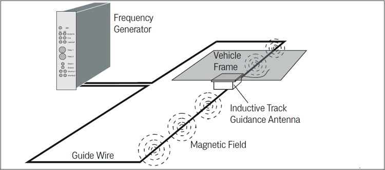
Sketch: Functional principle
A frequency generator feeds a current into a guide wire installed in the ground. Along this wire an alternating magnetic field is generated. When the sensor is moved along the guide wire two characteristic voltages are induced in its horizontal coils and evaluated. Thus for each frequency a sum and difference signal is calculated. Usum is used to detect whether a track is available (signal Detect when a threshold is exceeded). Udiff shows maxima at both sides of the wire and crosses zero directly above the wire. Udiff is used to control the vehicle.
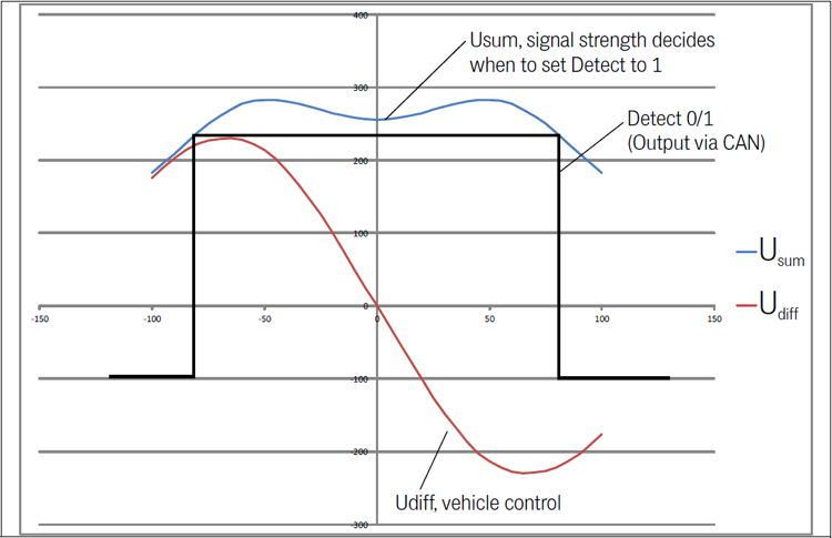
Diagram: Induced voltages, example for one of the six frequencies
Downloads
| Attachment | Filesize – | Uploaded |
|---|---|---|
| 344.2 KB | 26.10.2023 | |
| 1.97 MB | 26.10.2023 | |
| 13.45 KB | 26.01.2023 | |
| 2.86 KB | 20.05.2019 | |
| 1.52 KB | 07.05.2018 |