

Serial/Parallel Interface
Overview
- Interface for the transmission of data from Götting transponder antennas with serial data interface to PLC with digital inputs
- Variants for RS 232 and RS 422 (see table Variants on the back)
- Housing for top hat rail mounting (switch cabinet)
- Power supply +24V
- LED to indicate data transmission
- Output of transponder code (16 bit), Data_Ready and Data_Valid (1 bit each)
- Depending on variant and transponder antenna: analog output ±10V lateral deviation
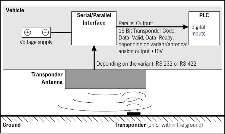
Connection example
The serial/parallel interface allows the transmission of the transponder code of a Götting transponder antenna connected via the serial interface – depending on the variant RS 232 or RS 422 – to a PLC with digital inputs. The interface comes in a housing suitable for top hat rail mounting.
The telegrams of the transponder antenna are received via the serial input of the interface. For control purposes, an LED is visible through the transparent cover. It lights up when serial telegrams are decoded. These telegrams are only generated by the antenna if there is a transponder in the field.
From the telegrams the transponder code is converted into a 16 bit parallel output. The code is present at the outputs until a new code is received.
In addition, 10 ms after the code bits are available a Data_Ready pulse of 100 ms length is generated when the antenna crosses a transponder. This means that the same transponder generates a new Data_Ready pulse when it re-enters the antenna field (e.g. due to a change of direction).
The Data_Valid signal indicates whether there is a transponder under the antenna. If there is no transponder in the field, 0 V is output. The parallel outputs, Data_Ready and Data_Valid are switched against 24V when activated and are not current limited. They are also not electrically isolated.
With the antennas of the types HG G-98810, HG G-98820, HG G-98830 and HG G-98850, the lateral deviation in the direction of travel is also output as an analog voltage in the range ±10 V if the antenna parameters are set accordingly.
Downloads
| Attachment | Filesize – | Uploaded |
|---|---|---|
| 201.42 KB | 17.06.2020 |